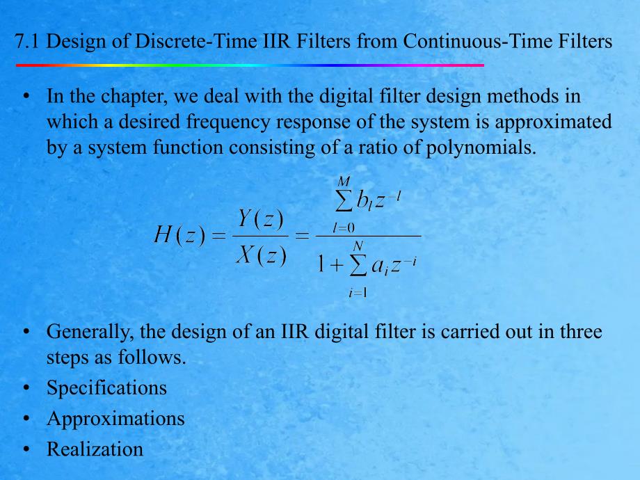
1、Digital Signal ProcessingChapter 7Filter Design Techniques7.1 Design of Discrete-Time IIR Filters from Continuous-Time FiltersIn the chapter, we deal with the digital filter design methods in which a desired frequency response of the system is approximated by a system function consisting of a ratio of polynomials.Generally, the design of an IIR digital filter is carried out in three steps as follows.SpecificationsApproximationsRealization7.1 Design of Discrete-Time IIR Filters from Continuous-Ti
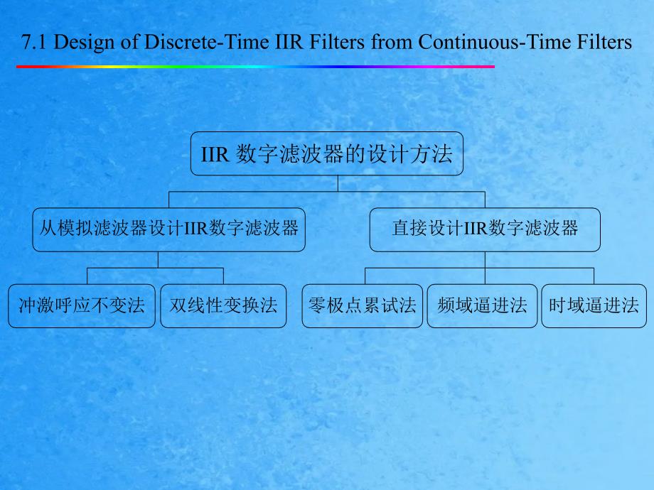
2、me FiltersIIR 数字滤波器的设计方法从模拟滤波器设计IIR数字滤波器直接设计IIR数字滤波器冲激呼应不变法双线性变换法零极点累试法频域逼进法时域逼进法Figure 1 Ideal magnitude specifications for digital lowpass filter理想滤波器的幅度特性有理想、陡截止的通带和无穷大衰减的阻带两个范围,如图1所示,这显然是无法实现的,由于它们的单位取样呼应均是非因果和无限长的。实际中只能用一种因果可实现的滤波器去与之逼近,使其满足给定的误差容限。一个实践滤波器的幅度特性在通带中允许有一定的动摇,阻带衰减那么应大于给定的衰减要求,且在通带与阻带之间允许有一定宽度的过渡带,如图2所示。 w-2p-p0p2pFigure 2 Magnitude specifications for digital lowpass filtertransition bandpassbandstopbandLowpass filter specificationPassband通带 The frequency range of 0 pc is calle
3、d the passband;pc is the passband cutoff frequency通带截止频率;p is the passband tolerance, that isStopband阻带 The frequency range of sc is called the stopband;sc is the stopband cutoff frequency阻带截止频率;s is the stopband tolerance, that isTransition bandThe frequency range of pc sc is called the transition band;Lowpass filter specificationMaximum passband attenuation pMinimum stopband attenuation pCommonly, the maximum magnitude response is assumed to be normalized to unity. For a lowpass filter, we hav
4、eDesign Stages for Digital FilterDesign stagesAnalog filter approximations, including Butterworth, Chebyshev and elliptic.Continuous-time to discrete-time transformation, including impulse invariance and bilinear transformation.Frequency transformations, that is, transforming a lowpass filter into a highpass or bandpass or bandstop filter.1 Analog Butterworth巴特沃思Lowpass FiltersThe Butterworth lowpass filter has several properties:All poles, and no zero.No ripples波纹 in the passband and stopband.T
5、he Butterworth lowpass filter is defined in a magnitude-squared function幅度平方函数:where N is a positive integer and is called the order of the filter, c is the passband cutoff frequency1 Analog Butterworth Lowpass FiltersBecause The cutoff frequency c is called the half-power frequency point of the filter.The maximum passband attenuation is the frequency c is also called 3-dB cutoff frequency or 3-dB bandwidth of the filter.1 Analog Butterworth Lowpass FiltersIn practical applications, the analog l
6、owpass filter is specified by the specifications as follows:pc: the passband cutoff frequency in rad/s;p: the maximum passband attenuation in dB;sc: the stopband cutoff frequency in rad/s;s: the minimum stopband attenuation in dB;To use the Butterworth lowpass filter to approximate a lowpass filter, we should obtain the order N and the 3-dB cutoff frequency c.1 Analog Butterworth Lowpass FiltersThe magnitude response of the filter isThe maximum passband attenuation p arrives at =pc, which is rep
7、resented asThe minimum stopband attenuation s arrives at =sc, which is represented as(7.141)(7.142)(7.140)1 Analog Butterworth Lowpass FiltersSolving the above two equations, we have1 Analog Butterworth Lowpass FiltersThere are two choices to determine cSubstituting N in Eq.(7.141), we have Using this formula to determine c, p is exactly met at =pc and s is exceeded for the stopband, provided that p3dB.Substituting N in Eq.(7.142), we have Using this formula to determine c, s is exactly met at =
8、sc and p is exceeded for the passband, provided that s3dB.1 Analog Butterworth Lowpass FiltersTo determine the transfer function Ha(s) of the filter, we substitute s = j, thereforeThe poles of the magnitude-squared function Ha(s)Ha(-s) are given by Figure 3 shows all the poles when N = 3.Figure 3 Pole plot for a third-order Butterworth filterk = 0k = 1k = 2k = 3k = 4k = 5j1 Analog Butterworth Lowpass FiltersThe 2N poles equally spaced in angle on a circle in the s-plane. They are symmetric about
9、 the imaginary axis.In order to obtain a stable system, we choose the n poles on the left-side of the s-plane. Then, we get the transfer function as follows where1 Analog Butterworth Lowpass FiltersThe attenuation of the Butterworth approximation increases monotonically单调地with frequency. And it increases very slowly in the passband and quickly in the stopband.If one wants to increase the attenuation one has to increase the filter order.The 3-dB bandwidth is unrelated to the filter order.Figure 4
10、 The magnitude-frequency response of Butterworth Lowpass Filters 2 Analog Chebyshev切贝雪夫Lowpass FiltersThe Chebyshev-I lowpass filters have equiripple等波纹的 magnitude response in the passband and monotonic单调的 magnitude response in the stopband.The magnitude-squared response of an analog Chebyshev-I lowpass filter is given bywhere N is the order of the filter, is a positive and less than unity number which is the passband ripple factor, c is the passband cutoff frequency at which the attenuation of
11、the magnitude response is not necessary to be 3-dB. The function TN(x) is an Nth-order Chebyshev polynomial defined by(7.147)2 Analog Chebyshev Lowpass FiltersThe characteristics of the Chebyshev-I filters are as follows: At = 0, |Ha(j0)| = 1 for N odd and |Ha(j0)| = for N even;At =c, |Ha(jc)| = for all N;Within the passband of 0c, |Ha(j)| oscillates between 1 and ;For c, |Ha(j)| approaches zero monotonically and rapidly;At =s (the stopband cutoff frequency), |Ha(js)| = 1/A.Figure 5 Analog Cheby
12、shev Lowpass Filters2 Analog Chebyshev Lowpass FiltersIn the design of Chebyshev-I lowpass filter, the specifications are given by:c: the passband cutoff frequency in rad/s;p: the passband ripple in dB;s: the stopband cutoff frequency in rad/s;s: the minimum stopband attenuation in dB;To design the filter, the order N and ripple factor should be determined.2 Analog Chebyshev Lowpass FiltersSince Then And Therefore 2 Analog Chebyshev Lowpass FiltersTo obtain the transfer function Ha(s) of the Che
13、byshev-I filter, we substitute =s/j into Eq.(7.147) (p19), and then we getThere are 2N poles of the magnitude-squared function Ha(s)Ha(-s), They are spaced on a ellipse in the s-plane and symmetric about the imaginary axis.In order to obtain a stable system, we choose the N poles on the left-side of the s-plane and get the transfer function as follows.2 Analog Chebyshev Lowpass Filterswhereand 两种典型模拟滤波器两种典型模拟滤波器:Butterworth巴特沃思滤波器:幅频特性单调下降,但衰减特性较差;Chebyshev切贝雪夫滤波器:在通带或阻带中幅频特性单调下降,在阻带或通带中有波纹,衰减特性
14、好于巴特沃思滤波器;Analog-to-Digital Filter Transformations The continuous-time to discrete-time transformations include three steps:Transformations of specifications in discrete-time domain into ones in continuous-time domain.Designing the analog filter according to the specifications in continuous-time domain.Transform the filter in s domain into the one in z domain.The main methods of transformations have two kinds:Impulse-invariance methodBilinear transformation methodz transform and Laplace transfor
15、mLaplace transformz transformThe Laplace transform of x(nT) isTherefore the relationship between the Laplace transform and z transform of x(nT) isz transform and Laplace transformLet and The relationship between r and If = 0 s 平面的虚轴, r = 1z平面单位圆上; If 0 s 平面的右半平面, r 1z平面单位圆外; If 0 s 平面的左半平面, r 1z平面单位圆内.The relationship between and : = T If = 0 s 平面的实轴, = 0 z平面正实轴 = 0 s 平面平行于实轴的直线, = 0T z平面始于原点角度为 = 0T 的辐射线.z transform and Laplace transform 从 /T 增长到 /T,相应的, 从 增长到 ,即 s 平面宽为 2/T 的一个程度条带相当于 z 平面辐角转了一
16、周,即整个 z 平面。因此 每添加一个抽样角频率 s = 2/T,那么 添加 2。所以从 s 平面到 z 平面的映射是多值映射。7.1.1 Filter Design by Impulse InvarianceThe transfer function of the analog filter can be expressed in terms of a partial-fraction expansion as followsThe corresponding impulse response is7.1.1 Filter Design by Impulse InvarianceSampling the analog impulse response, we can obtain the discrete-time impulse responseThe corresponding discrete-time transfer function iss 平面的单极点 s = pl 变换为 z 平面上 z = eplT 处的单极点;Ha(s) 与 H(z) 的部分分式的系数是一样的;假
17、设模拟滤波器是稳定的,即一切极点 s = pl 的实部小于零,那么一切 z = eplT 均在单位圆内,即变换后的数字滤波器也是稳定的。7.1.1 Filter Design by Impulse Invariance7.1.1 Filter Design by Impulse InvarianceIn order to obtain the same passband gain for the continuous- and discrete-time filters, we should use the following expression for Hd(z):ExampleTransform the continuous-time lowpass filter transfer function given byinto a discrete-time transfer function using the impulse invariance transformation method with s = 10 rad/s. Solution Example (cont.)E
18、xample (cont.)7.1.2 Bilinear TransformationThe bilinear transformation method avoids the problem of aliasing.In the bilinear transformation method, the entire s-plane is mapped into the entire z-plane.The left half s-plane maps into the interior of the unit circle in the z-plane;The right half s-plane maps into the exterior of the unit circle in the z-plane;The imaginary axis of the s-plane maps onto the unit circle;7.1.2 Bilinear TransformationThe bilinear transformation is defined asIf the con
19、tinuous-time transfer function is Ha(s), thenFrequency transformation relation 7.1.2 Bilinear TransformationThat isSince We should choose7.1.2 Bilinear TransformationIn conclusion, the bilinear transformation of a continuous-time transfer function into a discrete-time transfer function isTherefore the bilinear transformation maps analog frequencies into digital frequencies as follows:For high frequencies, this relationship is highly nonlinear.The bilinear transformation method avoids the problem
20、 of aliasing, but the price paid for this is the introduction of a distortion in frequency axis, known as the warping. 7.1.2 Bilinear TransformationThe warping effect can be compensated by prewarping the frequency specifications. The steps arePrewarp the passband and stopband frequencies and obtain ap and ar through the following mapping:Generate Ha(s) satisfying the specifications for the frequencies ap and ar ;Obtain Hd(z) by replacing s with in Ha(s).7.2 Design of FIR Filters by WindowingBasi
21、c conceptionIn order to design the frequency responses satisfying the prescribed specifications, the filter order and multiplier coefficients should be determined.Characteristics of FIR filtersIt is possible to obtain exact linear phase.FIR systems are always stable.Fast algorithms such as FFT can be used.A higher order means more delays, multipliers and adders.Design approaches frequency sampling, window functions, maximally flat approximation.Ideal characteristics of standard filtersFour commo
22、nly used FIR filtersLowpass filtersHighpass filtersBandpass filtersBandstop filtersFourier transform pairFour ideal filters lowpassFrequency responseImpulse response1Figure - impulse response of lowpass filterFour standard filters highpassFrequency responseImpulse response1Figure - impulse response of highpass filterFour standard filters bandpassFrequency responseImpulse response1Figure - impulse response of bandpass filterFour standard filters bandstopFrequency responseImpulse response1Figure -
23、 impulse response of bandstop filterNotesThe durations of the impulse responses of the four kinds of filters are infinite. The impulse responses are noncausal.So, all these four kinds of filters are ideal ones and can not be realized.Properties of Linear Phase FIR FiltersThe linear-phase FIR filters:This equation shows that the h(n) of a linear-phase FIR filter is symmetric or antisymmetric about M/2. There are four kinds of linear-phase FIR filters, which is shown in the figures.Properties of L
24、inear Phase FIR Filtersnh(n)2103 4 5 6 7 8nh(n)2103 4 5 6 7 8 9nh(n)2103 45 6 7 8nh(n)2103 45 6 7 8 9symmetricantisymmetricM evenM oddType IType IIType IIIType IVFrequency sampling频率采样法工程上,常给定频域上的技术目的,所以采用频域设计更直接。根本思想:使所设计的FIR数字滤波器的频率特性在某些离散频率点上的值准确地等于所需滤波器在这些频率点处的值,在其它频率处的特性那么有较好的逼近。Step 1Step 2Step 3Step 4采样采样IDFTFTFrequency sampling1)Let Hd() be the desired frequency response.2)The design approach of frequency sampling is just to sample the Hd().3)Suppose that H(k) are samples of the Hd(), i.
25、e.4)Let5) then A(k) = |H(k)|6) (k) = argH(k)7) A(k) is the magnitude of the H(k) and (k) its phase.Frequency sampling3)We can get the impulse response h(n) from H(k) using IDFT 4) 5) 6)Then the z transform of the designed FIR filter7) 8) we can also get the frequency response H(e j) For exampleRipples in the passband and stopband. Frequency samplingIf the linear phase is required, A(k) and (k) must satisfy the conditions for linear phase.Four types of linear-phase filtersType I: the order M is e
26、ven and the h(n) is symmetric.Type II: the order M is odd and the h(n) is symmetric.Type III: the order M is even and the h(n) is antysymmetric.Type IV: the order M is odd and the h(n) is antysymmetric.Relation between the length of h(n), N, and order MN = M +1Frequency sampling type I In this case, the order M is even and the h(n) is symmetric.ReviewThe frequency responseH() is symmetric about = 0 and = .Frequency sampling type I Phase MagnitudeFrequency sampling type IIIn this case, the order
27、M is odd and the h(n) is symmetric.ReviewThe frequency responseH() is symmetric about = 0 and antisymmetric about = . So, H() = 0, at = .Frequency sampling type IIPhase MagnitudeBecause H() = 0, at = , highpass and bandstop filters cannot be realized in Type II filters.Frequency sampling type III In this case, the order M is even and the h(n) is antisymmetric.ReviewThe frequency responseH() is antisymmetric about = 0 and = . So, H() = 0, at = 0 and = .Frequency sampling type III Phase MagnitudeB
28、ecause H() = 0, at = 0 and = , lowpass, highpass and bandstop filters cannot be realized in Type III filters.Frequency sampling type IV In this case, the order M is odd and the h(n) is antisymmetric.ReviewThe frequency responseH() is antisymmetric about = 0 and symmetric at = . So, H() = 0, at = 0.Frequency sampling type IV Phase MagnitudeBecause H() = 0, at = 0, lowpass and bandstop filters cannot be realized in Type IV filters. h(n)MH()的对称性可实现的滤波器I 型偶对称偶数在 = 0 及 = 处偶对称四种滤波器都可设计II 型偶对称奇数在 = 0 处
29、偶对称,在 = 处奇对称不能设计高通和带阻,可设计低、带通滤波器III 型奇对称偶数在 = 0 及 = 处奇对称不能设计低通、高通和带阻,只能设计带通滤波器IV 型奇对称奇数在 = 0 处奇对称, 在 = 处偶对称不能设计低通和带阻,可设计高通、带通滤波器Design of Linear-Phase FIR filters using windowsAll ideal filters have infinite duration, so they can not be realized. Truncating the impulse response h(n), we can get its approximation with finite duration.where M is the filter order and assuming that it is even. The transfer function isDesign of Linear-Phase FIR filters using windowsAfter h(n) is truncated, the system
30、 is still noncausal. In order to make it causal, we can shift it right by M/2, without either distorting the filter magnitude response or destroying the linear-phase property.There are ripples close to the band edges in the magnitude response. These ripples are referred to as Gibbs oscillations. And the amplitudes of Gibbs oscillations do not decrease even the filter order M is increased.Design of Linear-Phase FIR filters using windowsMultiplying the impulse response h(n) by a window function w(
31、n), that is,we can improve the magnitude response.The multiplication in the time domain corresponds to periodic convolution integral of H(ej) and W(ej) in the frequency domain, that is Magnitude responses of a window function|W(ej)|Main lobeSide lobe主瓣旁瓣Magnitude responses of a window function正肩峰正肩峰负肩峰负肩峰Design of Linear-Phase FIR filters using windows最大旁瓣的相对幅度越小即能量越集中在主瓣上,起伏振荡的幅度越小,阻带衰减越多;窗函数频谱的主瓣越窄,过渡带越陡;这两者是矛盾的。|W(ej)|Main lobeSide lobe主瓣旁瓣1 Rectangular window矩形窗The rectangular window functio
32、nThe frequency response of the rectangular window1 Rectangular window2 Triangular window and Bartlett windowThe triangular window functionThe Bartlett window function2 Triangular window三角形窗Bartlett window3 Hamming and Hanning windowsThe window function with 0 1.When =0.54, it is called the Hamming window海明窗.When =0.5, it is called the Hanning window汉宁窗.Hamming windows海明窗3 Hamming and Hanning windowsThe transition band过渡带of the Hamming window is larger than that of the rectangular windows, due to
33、 its wider main lobe.The ratio between the amplitudes of the main and secondary lobes of the Hamming window is much larger than for the rectangular window. So the stopband attenuation衰减for the Hamming window is larger than the attenuation for the rectangular window.Hanning windows汉宁窗4 Blackman window布莱克曼窗The Blackman windowBlackman windowCommonly used windows in time domainnw(n)0RectangularBartlettHammingHanningBalckman矩形窗矩形窗三角形窗三角形窗海明窗海明窗汉宁窗汉宁窗布莱克曼窗布莱克曼窗矩形窗、三角性矩形窗、三角性窗、海明窗、汉窗、海明窗、汉宁窗、布莱克曼宁窗、布莱克
34、曼窗随着窗外形的窗随着窗外形的变化,旁瓣衰减变化,旁瓣衰减加大,但主瓣宽加大,但主瓣宽度也加宽了;度也加宽了;ExampleUsing the rectangular, Hamming, Hanning, and Blackman windows, design a bandstop filter whose specifications are below M = 80 (order of the bandstop filter) p1 = 2000 rad/s (the first passband frequency) p2 = 4000 rad/s (the second passband frequency) s = 10000 rad/s (sampling frequency) Solution:Example (cont.)Example (cont.)From the figure, we should notice thatAs the ripple decreases and the stopband attenuation increases, the widt
35、h of the transition band increases accordingly when going from the rectangular to the Blackman window.5 Kaiser windowAll the window functions introduced so far have no control ability over the passband and stopband ripples. So when the ripple specifications are given, those window functions have little use.Kaiser and Dolph-Chebyshev windows can overcome such problems.When using Kaiser and Dolph-Chebyshev windows to design filters, not only the specification of passband and stopband frequencies s
36、hould be given, but also the passband and stopband ripples are provided.5 Kaiser window5 Kaiser windowThe Kaiser window function is defined asI0() is the modified zeroth order Bessel function of the first kind第一类变形零阶贝塞尔函数. The parameter is the key in designing filters and gotten by the specifications 越大,w(n)窗越窄,频谱的旁瓣越小,但主瓣宽度也相应添加.Kaiser window6 Dolph-Chebyshev windowThe Mth-order Chebyshev polynomial is defined asFor exampleRecurrence formula6 Dolph-Chebyshev windowThe Dolph-Chebyshev window is defined aswhere r is given by r = r/p and x0 byDolph-Chebyshev window窗函数法设计流程确定所需理想滤波器的频率呼应 Hd(ej) 及其冲激呼应 hd(n) Y选择窗函数 w(n) 及窗口长度 N加窗: h (n) = hd(n)w(n)结 束H(ej) = FTh(n) NH(ej) 满足要求?
《离散时间信号处理DSP第章ppt课件》由会员pu****.1分享,可在线阅读,更多相关《离散时间信号处理DSP第章ppt课件》请在金锄头文库上搜索。


